
- Published on
CH3. Data Transmission
- Authors

- Name
- seren-wib
Contents
- CH3. data transmission (how to turn data into signals and send them)
- 1. Data transmission media
- 1-1 Types of transmission media
- 1-2 Connection structure
- 1-3 Transmission direction
- 1-4 4 factors to consider when designing/selecting a medium
- 2. Signal representation
- 2-1 Analog vs Digital
- Sine wave
- 3. Frequency Domain (frequency-domain analysis)
- 3-1 Fourier analysis
- 3-2 Time domain vs frequency domain
- 3-3 Spectrum and Bandwidth
- 3-4 Why these concepts matter
- 4. Data Rate ↔ Bandwidth
- Why go digital
- 5. Transmission Impairments
- 5-1 Attenuation
- 5-3 Delay Distortion
- 5-4 Noise
- 6. Channel Capacity
- 6-1 What is Channel Capacity?
- 6-2 Two formulas for finding channel capacity
- 6-3 Which is more efficient to increase, Bandwidth or SNR?
- CH3. data transmission
CH3. data transmission (how to turn data into signals and send them)
1. Data transmission media
Transmitter ↔ Transmission medium ↔ Receiver
1-1 Types of transmission media
Classified by whether the signal travels only inside a physical medium (cable)
| Term | Examples |
|---|---|
| Guided media | Twisted pair, Coaxial cable, Optical fiber |
| Unguided media | Propagation through air, vacuum, etc. |
1-2 Connection structure
How the devices connected to the medium are arranged
- Direct link: no devices between the transmitter and receiver other than amplifiers or repeaters
- Amplifiers and repeaters are equipment that restores signal strength, so they are not counted as "intermediate devices"
- Point-to-Point: a direct link, with 2 devices sharing the medium
- Multi-point: more than two devices share the same medium
1-3 Transmission direction
Which direction does the signal flow? Can it flow both ways at once?
| Term | Simultaneous transmission | Bidirectional | Example |
|---|---|---|---|
| Simplex | x | x (one-way) | Radio broadcasting |
| Half duplex | x | O (taking turns) | Walkie-talkie |
| Full duplex | O | O | Telephone |
1-4 4 factors to consider when designing/selecting a medium
| Factor | Effect |
|---|---|
| Bandwidth | The wider the frequency range, the higher the data rate |
| Transmission impairments | Impairments such as attenuation limit the distance |
| Interference | Overlapping frequency bands distort or cancel the signal |
| Number of receivers | The more receivers, the more the signal is attenuated |
Frequency-domain graph

Amplitude ↑
     │     ┌───────────┐
     │     │           │
     │     │           │
     └─────┴───────────┴──────→ Frequency
          300Hz       3400Hz

          ←─── bandwidth ───→
              = 3100Hz
- attenuation: the signal weakens in proportion to distance
2. Signal representation
2-1 Analog vs Digital
- Analog signal
- A signal that changes continuously (can take infinitely many values)
- Examples: natural sounds, the human voice
- Directly affected by noise
- Hard to recover (once it's damaged, that's it)
- Digital signal
- A signal that changes in discrete steps, like a staircase
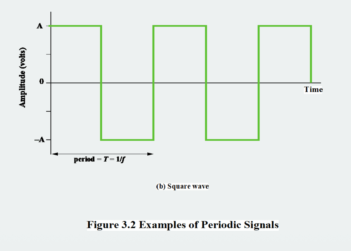
- Usually represented with two values (0 and 1, +v and -v)
- Range of values: discrete (usually 2)
- Indirectly affected by noise (bit errors)
- Easy to recover (you only need to decide whether it's 0 or 1)
Sine wave
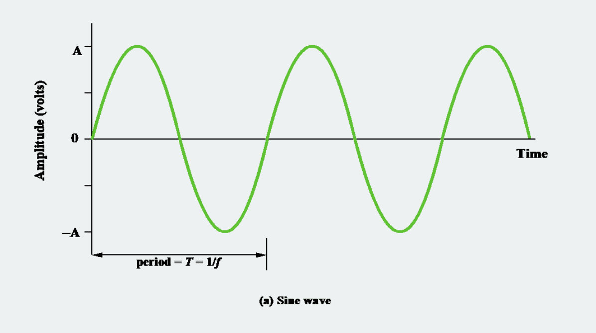
- Why sine waves matter: because every complex signal can be decomposed into a sum of sine waves
- Every signal we process, whether a human voice, digital bits or music, is ultimately a combination of sine waves
- The 3 parameters that define a sine wave
- Amplitude (A)
- The maximum magnitude of the signal
- The height along the y-axis
- Unit: volts (V)
- "How big the swing is"
- Frequency (f)
- Number of oscillations per second
- Unit: Hz (Hertz)
- The time for one oscillation = Period (T)
- Key formula: T = 1/f
- Phase (φ)
- Where within one period the signal starts
- Amplitude (A)
Amplitude ↑
        │      ╱╲
      A ┤    ╱    ╲
        │  ╱        ╲
        │╱            ╲
       0├──────────────────────→ Time
        │              ╲      ╱
     -A ┤                ╲  ╱
        │                  ╲╱
        ←──── T (period) ──→
- Wavelength (λ)
- How many meters does it travel in one cycle?
- If the signal's propagation speed is v:
- λ = v × T
One cycle
      ←──── λ (wavelength) ────→
   ┌─────────────────────────────┐
   │      ╱╲              ╱╲     │
   │    ╱    ╲          ╱    ╲   │
   │  ╱        ╲      ╱        ╲ │
   │╱            ╲  ╱            │
   │               ╲╱            │
   └─────────────────────────────┘
   x-axis: distance (space)
3. Frequency Domain (frequency-domain analysis)
3-1 Fourier analysis
- A mathematical operation that converts a time-domain signal into the frequency domain Every signal is a sum of sine waves of various frequencies
- The viewpoint of looking at a signal on the frequency axis instead of the time axis (the bandwidth graph)
Complex signal         Sum of sine waves

                   = 1Hz sine wave (large amplitude)
   ╱╲╱╲╱╲╱╲         + 3Hz sine wave (medium amplitude)
  ╱        ╲        + 5Hz sine wave (small amplitude)
 ╱          ╲       + 7Hz sine wave (smaller amplitude)
                    + ...
3-2 Time domain vs frequency domain
- Time graph
Amplitude ↑
     │  ╱╲    ╱╲╱╲
     │ ╱  ╲  ╱    ╲
     │╱    ╲╱
     ├──────────────→ Time (s)
     │
     y-axis: magnitude of the signal (amplitude)
     x-axis: time
- Frequency graph
Amplitude ↑
     │
   3 ┤ █
     │ █
   2 ┤ █     █
     │ █     █
   1 ┤ █     █     █
     │ █     █     █
     ├─────────────────→ Frequency (Hz)
       1Hz   3Hz   5Hz

     y-axis: magnitude of that frequency component
     x-axis: frequency
3-3 Spectrum and Bandwidth
Spectrum: the range of frequencies a signal contains
The example signal above consists of 1Hz, 3Hz and 5Hz, so spectrum = 1Hz ~ 5Hz
Absolute Bandwidth = (highest frequency) - (lowest frequency) = 5Hz - 1Hz = 4Hz
Effective Bandwidth: the narrow frequency range where the energy is concentrated
In general, plain "bandwidth" means effective bandwidth
Amplitude ↑
     │
     │  ████████
     │  ████████
     │  ████████
     │  ████████ █
     │  ████████ █  ▪
     ├─────────────────→ Frequency
        ←──────→
         effective
         bandwidth
        (most of the energy gathers here)
- DC (direct current) component: the 0 Hz component, a signal that does not change over time
3-4 Why these concepts matter
- Bandwidth isn't just a frequency range; it directly determines how much data can be sent over that medium
- Complex signal = needs many frequency components = needs wide bandwidth
Simple signal (slow changes):
   ╱╲      ╱╲
  ╱  ╲    ╱  ╲     → can be expressed with a few low frequencies → narrow bandwidth
 ╱    ╲  ╱    ╲

Complex signal (fast changes):
   ┌┐ ┌┐ ┌┐
   ││ ││ ││         → needs everything up to high frequencies → wide bandwidth
 ──┘└─┘└─┘└──
- Why does a square wave (digital signal) have infinite bandwidth?
- A digital signal is a square wave where 0 and 1 switch abruptly at right angles
- To build this right-angled shape from a sum of sine waves, you theoretically need infinitely many frequencies
- But in practice most of the energy is in the first few components, so it can be approximated with a finite bandwidth.
- However, the narrower the bandwidth, the more rounded the shape becomes, making 0 and 1 harder to tell apart
4. Data Rate ↔ Bandwidth
The larger the bandwidth, the higher the data rate
[1] Every transmission system has only a limited frequency band
                    ↓
[2] This limit restricts the data rate that can be sent over the medium
                    ↓
[3] A square wave (digital signal) has infinitely many frequency components
   (= needs infinite bandwidth)
                    ↓
[4] But most of the energy is concentrated in the first few components
                    ↓
[5] Limiting the bandwidth distorts the signal
By frequency
Original (pulses before transmission):
  ┌─┐ ┌──┐ ┌─┐
  │ │ │  │ │ │
──┘ └─┘  └─┘ └──    perfect square wave


Bandwidth limited to 500Hz:
   ╱╲    ╱╲
  ╱  ╲__╱  ╲___       almost a sine wave, hard to tell 0/1 apart


Bandwidth 900Hz:
   ╱╲   ╱╲╱╲
  ╱  ╲_╱     ╲       slightly angular shape


Bandwidth 1700Hz:
   ┌╲   ┌─╲
  ╱  ╲_╱   ╲___      similar to a square wave


Bandwidth 4000Hz:
   ┌─┐  ┌──┐ ┌─┐
  ─┘ └──┘  └─┘ └──   almost the original
Bandwidth ∝ Data Rate (directly proportional)
Intuitive analogy Bandwidth = number of lanes on a road Data Rate = number of cars passing per hour
Why go digital
| Reason | English | Key point |
|---|---|---|
| Digital technology | Digital technology | LSI/VLSI advances reduce the cost and size of digital circuits ↓ |
| Data integrity | Data integrity | Repeaters can restore the signal → no loss even over long distances |
| Capacity utilization | Capacity utilization | Multiplexing can be applied to high-bandwidth media like fiber and satellite |
| Security and privacy | Security and privacy | Easy to apply encryption |
| Integration | Integration | Voice, video and data handled the same way |
5. Transmission Impairments
Analog signal → degraded signal quality (a crackling radio) Digital signal → bit errors (0 misread as 1, 1 misread as 0)
Transmission Impairments
│
├─ 1. Attenuation
│
├─ 2. Delay distortion
│
└─ 3. Noise
   ├─ Thermal noise
   ├─ Intermodulation noise
   ├─ Crosstalk
   └─ Impulse noise
5-1 Attenuation
- The weakening of signal strength with distance.
- Weakening with distance
Start:  ████████████  (strong)
Middle: ████████      (weaker)
End:    ████          (even weaker)
- Happens differently depending on frequency (higher frequencies weaken faster)
After traveling the same distance:

Low-frequency component:  ████████  (weakened less)
Mid-frequency component:  █████     (medium)
High-frequency component: ██        (weakened a lot)
A digital signal is a sum of many frequencies, so if only the high frequencies weaken, the shape of the signal is ruined. This is called attenuation distortion.
So the receiver has 2 conditions to satisfy
- Strong enough to be detected
- Higher than noise
Solutions
| Method | Role |
|---|---|
| Amplifier | Boosts the weakened signal again (for analog) |
| Repeater | Regenerates the digital signal and sends it anew |
| Loading coil | Flattens the differences in attenuation across frequencies |
| Equalizer | Applies different amplification per frequency |
5-3 Delay Distortion
- Different frequency components arrive at different speeds
- Condition: occurs only in guided media (twisted pair, coaxial cable, fiber)
- Does not occur in wireless (in wireless (through the air), all frequencies travel at the same speed, the speed of light)
Departure (simultaneous):
   Low freq  ████
   Mid freq  ████
   High freq ████  → transmit

In transit (speed difference):
   Low freq  ━→
   Mid freq  ━━→ (a bit faster)
   High freq ━━━→ (faster)

Arrival (time difference):
   Low freq  ████      ← arrives late
   Mid freq   ████
   High freq   ████    ← arrives early

   → combine into a shape different from the original
A phase difference arises between the frequencies
The phase difference can cause Intersymbol Interference (ISI).
- Intersymbol Interference (ISI): after one bit ends, the tail of its signal spills into the next bit and interferes with reading the next bit
Bit string to send: 1 0 1 1
            ┌┐ ┌┐┌┐
            ││ ││││
            ┘└─┘└┘└

After delay distortion:
            ┌┐_┌┐┌┐
             ⌒⌒⌒⌒⌒⌒  ← the end of one bit leaks into the next bit

                → bit boundaries blur → hard to tell 0/1
5-4 Noise
Unwanted signals that intrude between the transmitter and the receiver.
Noise is the main limiting factor on communication system performance.
Attenuation and delay distortion can be compensated for, but noise fundamentally cannot be removed. So it is the ultimate limit of communication. The Shannon formula in step 6 defines exactly this limit mathematically.
4 kinds of noise
- Thermal Noise
- Caused by the thermal motion of electrons
- Distributed evenly across all frequencies (hence also called white noise)
- Cannot be removed
- Intermodulation Noise
- Caused by nonlinearity in the transmitter/receiver/medium
- An ideal system produces output proportional to input (linear), but in reality there is some nonlinearity, so when two frequencies go in, new frequencies are formed
Input signal:   f₁ = 100Hz, f₂ = 150Hz
                  ↓ (passes through a nonlinear system)
Output signal:  f₁ = 100Hz (normal)
                f₂ = 150Hz (normal)
                + 250Hz (= f₁ + f₂) ← newly created noise
                + 50Hz  (= f₂ - f₁) ← newly created noise
                + ...
- Crosstalk
- Caused by electrical coupling between adjacent lines
- The signal flowing in the neighboring wire leaks into my wire
Wire A: ━━━ signal A ━━━━━━━━━━
              ↕  (part of the signal leaks over through electrical coupling)
Wire B: ━━━ signal B + part of signal A ━━
- Solution: shielding. This is why UTP is more expensive than STP but has less crosstalk.
- Impulse Noise
Caused by external electromagnetic interference, lightning, etc.
Characteristics
- Irregular short spikes
- Short duration + high amplitude
- Non-continuous
To the human ear it's just heard for a moment, so why is it fatal for digital signals?
- Digital sends many bits in a short time, so even a single short spike corrupts several bits at once.
If even one bit is different, things like images get completely garbled, yet in reality bit errors inevitably occur. How do we manage them?
6. Channel Capacity
6-1 What is Channel Capacity?
- The maximum data rate that can be transmitted over a communication channel under given conditions
Channel Capacity (C)
= "the maximum number of bits per second this channel can carry"
= unit: bps (bits per second)
- The 4 factors that determine channel capacity
- Data Rate
- Unit: bps
- Meaning: the speed you want to send at
- Bandwidth
- Unit: Hz
- Meaning: the width of frequencies the channel passes
- Noise
- Unit: dB
- Meaning: the noise level of the channel
- Error rate
- Unit: ratio
- Meaning: how often errors occur
- Bandwidth ↑ → Data rate ↑ (learned in step 4)
- Bandwidth ↑ → cost ↑
- Noise ↑ → Error rate ↑ → effective Data rate ↓
- Noise is the most fundamental constraint (learned in step 5)
6-2 Two formulas for finding channel capacity
Nyquist Bandwidth
- How high can it go if there is no noise?
- The limit of an ideal noise-free channel
- Formula: C = 2B log₂ M
- C = channel capacity, B = bandwidth, M = number of signal levels (number of distinct signal elements)
- If M is increased to infinity, does the data rate become infinite too?
- In theory yes, but the spacing between signal levels narrows and it becomes vulnerable to noise
- So a real limit that accounts for noise is needed
Shannon Capacity
- How high can it go in the real world, with noise?
- The theoretical upper bound of a real channel
- Data rate ↑ → time per bit ↓ → even short noise corrupts many bits → error rate ↑
First, quantify the noise level SNR (Signal-to-Noise Ratio)
        signal power
SNR = ─────────
        noise power
Used as is, the numbers get too large or too small, so it is converted to dB (decibels)
SNR_dB = 10 × log₁₀ (signal/noise)- Shannon formula
- C = B × log₂ (1 + SNR)
- SNR: signal-to-noise ratio (a ratio, not dB!)
- Large SNR (little noise) → log₂(1+SNR) is large → C is large (can send a lot)
- Small SNR (lots of noise) → log₂(1+SNR) is small → C is small (can send only a little)
- Shannon capacity is an unreachable theoretical upper bound
6-3 Which is more efficient to increase, Bandwidth or SNR?
- Capacity is linear in bandwidth and logarithmic in SNR, so in theory increasing bandwidth is more efficient.
- But in practice, increasing SNR is easier
- So in reality, SNR is squeezed out to the point of diminishing returns, and then B is increased.