
- Published on
CH4. Transmission Media
- Authors

- Name
- seren-wib
Contents
- Transmission Media
- 7. Transmission media
- 7-1 Transmission media design factors
- 7-2 Overall media classification
- 8. Guided Media
- 8-1 Twisted Pair
- Characteristics
- UTP vs STP
- Cat category table
- Terms
- 8-2 Coaxial Cable
- Characteristics
- Transmission characteristics
- Uses
- 8-3 Optical Fiber
- How it works: total internal reflection
- 3 transmission modes (see image on p.45)
- Characteristics
- Uses
- 8-4 Guided Media overall comparison
- Transmission characteristics by medium (Point-to-Point)
- 9. Unguided Media (wireless)
- 9-1 Unguided Media concept
- Terms
- 9-2 Satellite Microwave
- Two configurations
- Why is 1~10 GHz optimal?
- Satellite communication applications
- VSAT — Very Small Aperture Terminal
- 10. Key summary
Transmission Media
7. Transmission media
7-1 Transmission media design factors
- The 4 factors covered in step 1
- Bandwidth, transmission impairments(attenuation), interference, number of receivers
7-2 Overall media classification
Frequency (Hz)  10²  10⁴   10⁶   10⁸   10¹⁰  10¹²  10¹⁴

[Guided]
  Twisted pair: ━━━━━━━━━━━━            (up to ~10⁶)
  Coaxial:           ━━━━━━━━━━         (10⁵~10⁸)
  Optical fiber:                 ━━━━━━ (around 10¹⁴)

[Unguided/Wireless]
  AM Radio:        ━            (~10⁶)
  FM Radio/TV:        ━━         (around 10⁸)
  Microwave:             ━━━     (10⁹~10¹¹)
  Infrared:                ━━    (10¹²~10¹⁴)
Key pattern: higher frequency -> more data possible -> more expensive medium*
8. Guided Media
8-1 Twisted Pair
Structure
━━━━━━━━━╱╲╱╲╱╲╱╲╱╲━━━━━━━━━
   (two copper wires twisted together)

   ←─ twist length ─→
Characteristics
- The cheapest and simplest medium
- The most widely used (telephone lines, LAN cables)
- Mainly used for communication inside buildings
- Smaller bandwidth than other media
- Limited distance (usually 100 m)
- Why twist? -> to cancel electromagnetic interference. If external noise affects both wires equally, it cancels out when the difference is taken
- Crosstalk is reduced by the same principle. The same crosstalk we learned in step 5 of ch3.
Two parallel wires:
   wire A ━━━━━━━━━  ← noise hits one side strongly
   wire B ━━━━━━━━━     → signal distortion

Two twisted wires:
   ╱╲╱╲╱╲╱╲      ← noise alternates between the two wires,
   ╲╱╲╱╲╱╲╱         affecting both equally → cancelled by differential
UTP vs STP
Classified by whether there is shielding
| Item | UTP (Unshielded) | STP (Shielded) |
|---|---|---|
| Shielding | None | Metal shielding |
| Price | Cheap | Expensive |
| Interference resistance | Weak | Strong |
| Data rate | Low | High |
| Uses | Ordinary telephone lines, LAN cables | High-speed communication, industrial |
- With shielding, external electromagnetic interference (EMI) is blocked by the shield, so the signal is protected.
Cat category table
| Category | Bandwidth | Main use |
|---|---|---|
| Cat 5e (Class D) | 100 MHz | 100 Mbps Ethernet |
| Cat 6 (Class E) | 250 MHz | 1 Gbps Ethernet |
| Cat 6A (Class E_A) | 500 MHz | 10 Gbps Ethernet |
| Cat 7 (Class F) | 600 MHz | 10 Gbps+ |
| Cat 7A (Class F_A) | 1000 MHz | Even faster |
Terms
- Insertion loss: loss as the signal passes through the cable (lower is better)
- NEXT (Near-End Crosstalk): crosstalk measured at the transmitting end (higher is better, since it means the other wire is far away)
- ACR (Attenuation-to-Crosstalk Ratio): ratio of crosstalk to attenuation (higher is better)
8-2 Coaxial Cable
The name "coaxial" means the inner and outer conductors share the same axis (co-axial) 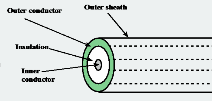
Cross-section:
Outer sheath
Outer conductor (shielding)
Insulation
Inner conductor (signal wire)
Characteristics
- Longer distances than twisted pair
- Can be shared by more devices (good for multi-point)
- Wider bandwidth (~500MHz)
- Resistant to external interference (self-shielded)
- More expensive than twisted pair
- Slower than optical fiber
Transmission characteristics
- Analog: an amplifier every few km (more often at higher frequencies)
- Digital: a repeater every 1 km (more often at higher speeds)
Uses
- Old TV cable (antenna → TV)
- Cable internet (modem → wall)
- Long-distance telephone (in the past)
- Ethernet LAN (10BASE2, 10BASE5 — old standards)
Its frequency characteristics are better than twisted pair, but performance is limited by attenuation and noise. LANs have all moved to twisted pair these days, but it is still in active use for cable TV/internet
8-3 Optical Fiber
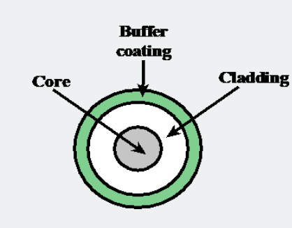
Cross-section:
Core: the center part light actually passes through. Glass or plastic.
Cladding: the layer surrounding the core. Lower refractive index than the core, so it traps the light and keeps it from leaking out.
Buffer: protects against external impact.
How it works: total internal reflection
cladding (low refractive index)
   ━━━━━━━━━━━━━━━━━━━━━━━━━━━
   ●→╲    ╱╲    ╱╲    ╱╲   →   ← light keeps reflecting at the
   ━━━━╲━╱━━╲━━╱━━╲━━╱━━━━━━     cladding boundary as it travels
              core
   ━━━━━━━━━━━━━━━━━━━━━━━━━━━
              cladding
When light enters at or above the critical angle, it is 100% reflected at the cladding boundary and trapped inside the core. So it can travel far without loss
3 transmission modes (see image on p.45)
[1] Step-index Multimode
   ━━━━━━━━━━━━━━━━━━━━━━━━━━━
       ╲    ╱╲    ╱╲    ╱╲   ← travels over multiple paths (modes)
        ╲╱    ╲╱    ╲╱        path lengths differ, so arrival times differ
   ━━━━━━━━━━━━━━━━━━━━━━━━━━━
   Input pulse: ▌    Output pulse: ╱─╲ (spread out)


[2] Graded-index Multimode
   ━━━━━━━━━━━━━━━━━━━━━━━━━━━
        ╱─╲    ╱─╲    ╱─╲     ← graded refractive index, smooth curves
       ╱   ╲  ╱   ╲  ╱   ╲       path differences shrink
   ━━━━━━━━━━━━━━━━━━━━━━━━━━━
   Input pulse: ▌    Output pulse: ╱╲ (less spread)


[3] Single Mode
   ━━━━━━━━━━━━━━━━━━━━━━━━━━━
        ━━━━━━━━━━━━━━━━━━     ← only one path (straight)
                                   almost no spreading
   ━━━━━━━━━━━━━━━━━━━━━━━━━━━
   Input pulse: ▌    Output pulse: ▌ (unchanged)
| Mode | Core size | Distance | Cost | Data rate | Uses |
|---|---|---|---|---|---|
| Step-index Multimode | Thick | Short | Cheap | Low | Short-distance LAN |
| Graded-index Multimode | Thick | Medium | Medium | Medium | Medium distance |
| Single Mode | Thin | Very long | Expensive | Very high | Long-haul backbone, submarine cable |
Characteristics
✓ Overwhelmingly wide bandwidth (THz range)
✓ Very low attenuation (40 km without repeaters)
✓ Not affected by electromagnetic interference (because it's light)
✓ Excellent security (hard to tap)
✓ Light, thin cable
✗ Expensive
✗ Hard to install/splice (optical axes must be aligned precisely)
✗ Two-way communication needs two strands
Uses
- Internet backbone networks
- Submarine cables (intercontinental communication)
- Carrier core networks
- High-speed links inside data centers
- FTTH (Fiber To The Home, home fiber internet)
8-4 Guided Media overall comparison
Attenuation comparison
How does attenuation change as frequency goes ↑?

Twisted pair:  frequency ↑ → attenuation rises sharply ↑  (limit around 10⁶Hz)
Coaxial:       frequency ↑ → attenuation ↑  (possible up to 10⁸Hz)
Optical fiber: almost flat and low     (even 10¹⁵Hz possible)

Optical fiber can go 20 times farther than other media.
Transmission characteristics by medium (Point-to-Point)
| Medium | Frequency range | Attenuation | Delay | Repeater spacing |
|---|---|---|---|---|
| Twisted pair (loading) | 0~3.5 kHz | 0.2 dB/km @ 1kHz | 50 μs/km | 2 km |
| Twisted pair (multipair) | 0~1 MHz | 0.7 dB/km @ 1kHz | 5 μs/km | 2 km |
| Coaxial cable | 0~500 MHz | 7 dB/km @ 10MHz | 4 μs/km | 1~9 km |
| Optical fiber | 186~370 THz | 0.2~0.5 dB/km | 5 μs/km | 40 km |
9. Unguided Media (wireless)
9-1 Unguided Media concept
Characteristics by frequency band |----|-----|----|
| Band | Frequency | Characteristics | Uses |
|---|---|---|---|
| Radio | 30 MHz ~ 1 GHz | omnidirectional | AM/FM radio, TV |
| Microwave | 1 GHz ~ 40 GHz | can be directional | satellite, microwave relay |
| Infrared | 3×10¹¹ ~ 2×10¹⁴ Hz | line-of-sight, short range | remote controls, short-range communication |
Terms
Omnidirectional:
   antenna ⊙
   radiates evenly in all directions
   → good for radio and TV broadcasting


Directional:
   antenna → → → →
   radiates concentrated in a specific direction
   → good for satellite communication, point-to-point links
9-2 Satellite Microwave
A satellite is a microwave relay station
[Ground station A]          [Ground station B]
    ^                            │
    │ (uplink)         (downlink)│
    |                            ↓
              ┌───────────┐
              │ satellite │  ← amplifies / converts the frequency of the received signal, then retransmits
              │ (repeater)│
              └───────────┘
Uplink: ground → satellite (5.925 ~ 6.425 GHz, "6 GHz band")
Downlink: satellite → ground (3.7 ~ 4.2 GHz, "4 GHz band")
This is called the 4/6 GHz band.
As it became saturated, the higher 12/14 GHz band also came into use.
Two configurations
[1] Point-to-point link
   Ground station A ←→ satellite ←→ Ground station B
   (only the two endpoints)

[2] Broadcast link
                  satellite
                 ╱  │  ╲
              ╱     │     ╲
        station1  station2  station3 ...
   (one transmitter → many receivers)
Why is 1~10 GHz optimal?
< 1 GHz:    lots of natural noise → poor signal quality
1~10 GHz:   ★ Sweet spot ★
> 10 GHz:   heavy atmospheric absorption + rain attenuation
Satellite communication applications
| Application | Description |
|---|---|
| Long-distance telephone | Formerly the mainstay of international calls (now ceded to fiber cables) |
| Private business networks | Dedicated corporate networks |
| TV distribution | DBS (Direct Broadcast Satellite, satellite broadcasting) |
| Global positioning | GPS (Navstar) |
VSAT — Very Small Aperture Terminal
A user terminal using a small satellite antenna. A system that lets even small shops and individual stores use satellite communication
[Ku-band satellite]
       /  │  ╲
      ╱   │   ╲
   [Hub  [remote 1] [remote 2]
   server] (POS terminal)
Used for retail payment systems, data collection from remote sites, etc.
10. Key summary
| Item | Twisted Pair | Coaxial | Optical Fiber | Wireless |
|---|---|---|---|---|
| Cost | ★ (cheap) | ★★ | ★★★ (expensive) | Varies |
| Bandwidth | Small | Medium | Very large | Varies |
| Distance | Short (2km) | Medium (1-9km) | Very long (40km) | Varies |
| Interference resistance | Weak | Medium | Very strong | Weak |
| Security | Weak | Medium | Strong | Very weak |
| Installation | Easy | Moderate | Difficult | Needs antennas |
| Main use | Phone lines, LAN | TV, old LAN | Backbone, long-haul | Wireless comm. |