
- Published on
CH3. Computer Organization and Data Processing
- Authors

- Name
- seren-wib
Contents
- 3.1 Computer Organization and Data Processing
- 3.1.1 Computer Architecture
- 3.2 Machine Language
- 3.2.1 Machine Language and Machine Instructions
- 3.2.2 Kinds of Machine Instructions
- 3.2.3 RISC and CISC
- 3.2.4 A Virtual Machine Language
- 3.3 Program Execution
- 3.4 Arithmetic and Logic Instructions
- 3.4.1 Logic Operations
- 3.4.2 Shift and Rotate Operations
- 3.4.3 Arithmetic Operations
- 3.4.4 Results and Status Information
- 3.5 I/O Control and Data Transfer
- 3.5.1 I/O Controllers and Peripheral Devices
- 3.5.2 Communication Between the CPU and I/O Controllers
- 3.5.3 Data Transfer Between Devices and Handshaking
- 3.5.4 Serial and Parallel Communication and I/O Interfaces
- 3.5.5 Polling and Interrupt
- 3.5.6 DMA (Direct Memory Access)
- 3.5.7 Sharing System Resources and the Limits of DMA
3.1 Computer Organization and Data Processing
Computer organization → memory hierarchy → how data is processed → the stored-program concept
3.1.1 Computer Architecture
1. Computer Organization and the CPU
Components of a computer
Component Role CPU Interprets and executes instructions, processes data Main memory Holds the running program and its data I/O devices Exchange data with the outside world Bus Carries information between components CPU
- Key roles: executing instructions, processing data, controlling operations
Part Role Control Unit Decodes instructions, generates signals that control the order of operations ALU Performs arithmetic, logic, comparison and bit-shift operations Register Temporarily holds values in immediate use and intermediate results - Example: for c = a + b, the control unit fetches the values and orders an addition, the registers hold a and b, and the ALU adds them and puts the result back in a register.
Registers
Why they are used: much faster than main memory
General-purpose registers: used for many things, such as variable values and calculation results
Special-purpose registers: have a fixed role. PC and IR are examples.
Special-purpose register What it holds PC(Program Counter) Address of the next instruction to fetch IR(Instruction Register) The instruction itself currently being decoded or executed - The CPU fetches the instruction at the address in PC, puts it in IR, and decodes it.
- PC normally moves to the next instruction's address, but a branch can change it to another address.
2. The Memory Hierarchy
Hierarchy table
- Speed, capacity and cost per bit trade off against each other → several kinds of memory are organized in layers
- Closer to the CPU means faster, smaller and more expensive; farther means slower, larger and cheaper → frequently used data stays close to the CPU
Level Distance from CPU Speed Capacity Cost per bit Register Closest Fastest Smallest Most expensive Cache memory Very close Very fast Small Expensive Main memory Middle Fast Large Moderate Secondary storage Far Relatively slow Very large Cheap Cache Memory: high-speed memory inside the CPU chip
- Temporarily stores copies of instructions and data likely to be used often
- Reduces main-memory accesses, easing the speed gap between the CPU and main memory
Cache hit / miss: when the CPU needs data, it checks the cache first
- Cache Hit: it is in the cache → use it right away
- Cache Miss: it is not → fetch it from a lower-level cache or main memory
Locality: the tendency to reuse recently used or nearby data. This is why caches work
- Temporal locality: data used recently will be used again soon. e.g. a loop counter i
- Spatial locality: when one location is used, nearby locations are used soon. e.g. scanning an array in order
- Arrays are stored contiguously → reading arr[0] also brings nearby elements into the cache → arr[1], arr[2] are hits
- Even with the same number of operations, run time changes with the memory access pattern
L1 / L2 / L3
Level Location / traits Speed Capacity L1 Closest to each core Fastest Smallest L2 Usually close to each core Fast Larger than L1 L3 Usually shared by several cores Relatively slow Largest - L1 → L2 → L3 → DRAM gets slower and larger (actual layout depends on the CPU design)
3. How Data Is Processed
Basic flow of a data operation: to compute, the CPU must bring the data inside the CPU
- Check the cache: on a cache hit use it right away; on a cache miss fetch it from main memory (DRAM)
- Load into registers: the ALU computes only with register values
- Compute in the ALU: the control unit decides the operation, the ALU computes with register data
- Store the result: it goes into a register first, then to cache and main memory if needed
- Data path: main memory ↔ cache ↔ register ↔ ALU
Bus: a shared communication path that carries information between the CPU, memory and I/O devices. Data, addresses and control signals all travel on it.
- Address bus (which slot), data bus (the value), control bus (read/write signal)
Memory read: CPU -bus(read signal, address)-> DRAM -bus(data)-> CPU
Memory write: CPU -bus(write signal, address, data)-> DRAM
- A read gets data back from DRAM; a write ends once the CPU has sent everything
Von Neumann Architecture: an architecture where programs and data are stored in the same main memory and the CPU fetches and processes them sequentially
- Von Neumann Bottleneck: when memory access is slow compared to CPU speed, the CPU spends time waiting for data
3.2 Machine Language
The CPU decodes and executes instructions expressed as bit patterns
3.2.1 Machine Language and Machine Instructions
Machine Language: instructions the CPU can understand and execute directly
Machine Instruction: one basic task the CPU performs
Structure of a machine instruction: what to do + which data to do it on
Part Meaning Example Opcode Kind of operation to perform Data move, store, operation, branch Operand Information about the target of the instruction Data, register number, memory address - e.g.
ADD R3, R1, R2→ ADD: addition (opcode), R1·R2: input operands, R3: destination register for the result
- e.g.
3.2.2 Kinds of Machine Instructions
Data Transfer instructions
- The original data does not disappear; the value is copied
- LOAD: memory → register (
LOAD R1, [A]) - STORE: register → memory (
STORE R1, [C]) - MOVE(MOV): copy between registers (
MOV R2, R1: R1's value into R2) - I/O instructions: exchange data with keyboard, disk and network devices. Handling differs by ISA and system
Arithmetic / Logic instructions
- ADD / SUB, MUL / DIV: the four arithmetic operations (
ADD R3, R1, R2: R3 ← R1 + R2) - AND / OR / XOR: bitwise logic operations
- SHIFT: move bits left/right
- ROTATE: put shifted-out bits back in on the other side
- ADD / SUB, MUL / DIV: the four arithmetic operations (
Control instructions: change the program's execution order
- Conditional Branch: change the next instruction based on a condition. Implements C's if, while, for
- Unconditional Jump: move to a given location without a condition. Function calls, loops and branches
- End program execution (HALT)
Addition example C = A + B: Memory A/B → Registers → ADD → Register → Memory C
Step Instruction Memory A into R1 LOAD R1, [A]Memory B into R2 LOAD R2, [B]R1 + R2 → R3 ADD R3, R1, R2R3 into memory C STORE R3, [C]Stop HALTDivision example C = A / B: Memory A, B → Registers → zero check → DIV → Register → Memory C
Step Instruction Memory A into R1 LOAD R1, [A]Memory B into R2 LOAD R2, [B]If R2 is 0, jump to error handling JUMP R2, DIV_ZEROR1 / R2 → R3 DIV R3, R1, R2R3 into memory C STORE R3, [C]Stop HALTEven one C statement runs as several machine instructions
3.2.3 RISC and CISC
ISA (Instruction Set Architecture): the contract between the CPU and programs
Two approaches to CPU instruction design
- RISC (Reduced Instruction Set Computer): centered on simple, regular instructions
- CISC (Complex Instruction Set Computer): supports varied, compound instructions
ARM architecture: a RISC-family ISA developed by Arm. Focuses on energy efficiency; the leading modern RISC family
3.2.4 A Virtual Machine Language
Virtual computer setup
- Main memory of 256 cells, addresses 00 ~ FF
- 16 general-purpose registers, numbered 0 ~ F. Plus PC and the instruction register (IR)
- Instruction length 16 bits = 2 bytes = 4 hex digits
Instruction structure
- One hex digit = 4 bits
- op-code: the first 4 bits, which instruction it is (16 possible instructions)
- operand: the remaining 12 bits = 4 bits (register number) + 8 bits (memory address/value)
Bit position 15 ~ 12 11 ~ 8 7 ~ 0 Field op-code Register Address/value 35A7 0011 (3) STORE 0101 (5) R5 1010 0111 (A7) Instruction Form Meaning 1RXY LOAD R, MEM R ← value at address XY 2RXY LOAD R, VAL R ← value XY (1 byte) 3RXY STORE R, MEM Address XY ← value of R 40RS MOVE R, S S ← value of R 5RST ADD R, S, T R ← S + T (two's complement addition) 6RST ADDF R, S, T R ← S + T (floating-point addition) 7RST OR R, S, T R ← S OR T 8RST AND R, S, T R ← S AND T 9RST XOR R, S, T R ← S XOR T AR0X ROT R, X Rotate R right by X bits BRXY JUMP R, ADDR Branch to address XY if R = R0 B0XY Unconditional branch Branch to address XY (always true since R0 = R0) C000 HALT Stop Decoding examples
- 35A7: 3 = STORE, 5 = register 5, A7 = address → store the contents of register 5 at address A7
- B34C: if register 3 equals register 0, branch to address 4C
- B04C: branch to address 4C unconditionally
- When a branch is taken, PC is set to the given address instead of incrementing
Usage example: c = a + b
Machine instruction Description 156C LOAD the value at address 6C into register 5 166D LOAD the value at address 6D into register 6 5056 Register 5 + register 6 (two's complement addition) → register 0 306E STORE register 0's value at address 6E (STORE always writes to memory) C000 Stop Decoding order: check the opcode → split the fields → interpret registers/addresses → trace the data flow
3.3 Program Execution
A program is loaded into main memory, then runs by fetching, decoding and executing the instruction PC points to, one at a time
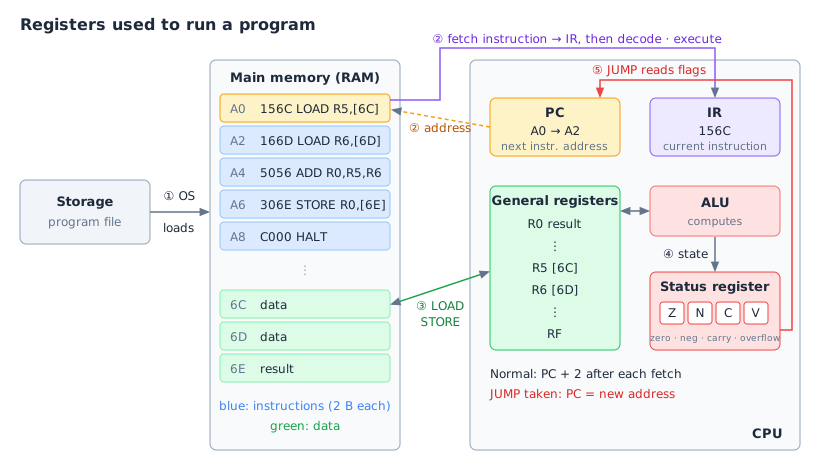
① Run request → the OS loads it into RAM
② Machine cycle: fetch → decode → execute, repeated (until HALT)
- Fetch: the instruction at the address in PC → IR, and PC immediately goes +2 (an instruction is 2 B and a cell is 1 B, so two cells)
- Decode: the control unit reads the op-code at the front of IR and decides what to do (e.g.
1→ LOAD) - Execute: the actual action (data move, operation, store, branch)
③ Values to compute and their results live in general-purpose registers (RAM ↔ register via LOAD and STORE)
④ Whether the result is zero, negative, carried out or overflowed is recorded in the status register flags (Z·N·C·V)
⑤ Branch: JUMP reads the flags and changes PC to another address →
if,whileand function calls are all built on this- Controlling program flow = deciding where to send PC
Example:
[6C] + [6D] → [6E]
| PC at start | Instruction | After fetch | Decode | Execute |
|---|---|---|---|---|
A0 | 156C | PC=A2 | LOAD R5, [6C] | R5 ← [6C] |
A2 | 166D | PC=A4 | LOAD R6, [6D] | R6 ← [6D] |
A4 | 5056 | PC=A6 | ADD R0, R5, R6 | R0 ← R5 + R6 |
A6 | 306E | PC=A8 | STORE R0, [6E] | [6E] ← R0 |
A8 | C000 | PC=AA | HALT | Program ends |
3.4 Arithmetic and Logic Instructions
CPU operations are bit-pattern transformations done by the ALU within a fixed number of bits + recording status flags
Kinds of operation instructions
Kind Typical instructions Main use Logic operations AND,OR,XOR,NOTTest, set, flip specific bits Shift operations SHL,SHR,SAR,ROL,RORMoving bits, bit manipulation Arithmetic operations ADD,SUB,MUL,DIVInteger and real-number calculation Comparison operations CMP,TESTCheck results before a conditional branch
3.4.1 Logic Operations
Logical Operation: an operation done independently on each bit position. Used to manipulate bit states rather than compute magnitudes
Operation Result is 1 when Use in bit masking Example ( x = 01011001)AND ( &)Both bits are 1 Keep (extract) only the wanted bits / clear the rest to 0 01011001 & 00001111 = 00001001(extract low 4 bits)OR ( |)At least one is 1 Set specific bits to 1 01011001 | 10000000 = 11011001(set the top bit)XOR ( ^)The bits differ Flip specific bits (only where the mask is 1), compare values 01011001 ^ 00000001 = 01011000(flip the lowest bit)NOT ( ~)Opposite of the input bit Flip every bit ~01011001 = 10100110Checking bit states: check whether a specific bit is 0 or 1, like a switch (using
AND)- Odd/even check: test the rightmost bit (LSB) with
n & 1→1means odd (0111 & 0001 = 0001),0means even (0110 & 0001 = 0000) - Uses: device ready status, file access permissions, whether an option is on, storing many true/false states in one integer
- Odd/even check: test the rightmost bit (LSB) with
3.4.2 Shift and Rotate Operations
- Shift and Rotate: move bits left/right. A plain shift drops the bits pushed out and fills the empty spots; a rotate puts the pushed-out bits back in at the other end
| Kind | Direction / instruction | Filling empty bits | Effect and main use |
|---|---|---|---|
| Logical left shift | SHL (<<) | Always inserts 0 on the right | ×2 effect within range (bits beyond the width are lost → not always double) |
| Logical right shift | SHR (>>) | Always inserts 0 on the left | ÷2 quotient effect on unsigned integers (54(00110110) >> 1 → 27(00011011)) |
| Arithmetic right shift | SAR | Copies the top sign bit (MSB) into the left | Keeps the sign of signed (two's complement) integers + ÷2 effect (-12(11110100) → -6(11111010)) |
| Rotate left/right | ROL / ROR | Puts the pushed-out bit back at the other end | Rearranging bits, mixing bits in encryption, hash functions (ROL: MSB→LSB, ROR: LSB→MSB) |
3.4.3 Arithmetic Operations
Integer arithmetic: in the end a combination of binary addition, subtraction and shifts
- Addition (
ADD): the ALU computes each bit's sum and carry - Subtraction (
SUB): instead of a separate subtraction circuit, adds the two's complement and reuses the adder (A - B = A + (-B)) - Multiplication (
MUL): Shift + Add, checking each bit, shifting left and adding (e.g.13 × 5 = 13 × (4 + 1) = (13 << 2) + 13) - Division (
DIV): Shift + Subtract, repeatedly subtracting the divisor to decide each quotient bit
- Addition (
Examples (8-bit)
Subtraction: 7 − 3
 3   = 00000011
-3   = 11111100 + 1 = 11111101   (flip, then +1: two's complement)

  00000111   (7)
+ 11111101   (-3)
-----------
1 00000100   → drop the leading 1 that overflowed → 00000100 = 4
Multiplication: 13 × 5
5 = 101 → positions with a 1: 2², 2⁰
13 << 2 = 00110100   (52, 13×4)
13 << 0 = 00001101   (13, 13×1)
          --------
          01000001   (65)
Division: 13 ÷ 5 (
1101 ÷ 101)1 < 101 → quotient 0 11 < 101 → quotient 0 110 ≥ 101 → quotient 1, 110 - 101 = 1 11 < 101 → quotient 0 quotient 0010 = 2, remainder 11 = 3Integer vs floating-point operations
Aspect Integer operation ( 29 + 13)Floating Point operation ( 3.14 + 2.75)Representation Integer bit pattern Sign, exponent, mantissa Process Centered on binary addition (computed directly) Compare and align exponents (shift the smaller mantissa) → add/subtract mantissas → normalize the result → round Main problem Overflow Rounding error, loss of precision (why 0.1 + 0.2 == 0.3may not be true)Floating-point example (
1.5 + 0.75)1.5 = 1.1 × 2⁰ 0.75 = 1.1 × 2⁻¹ 1) Align exponents: bring the smaller one to 2⁰ → 0.11 × 2⁰ (mantissa shifted right by one) 2) Add mantissas: 1.10 + 0.11 = 10.01 × 2⁰ 3) Normalize: 1.001 × 2¹ (move the point one place, exponent +1) = 2.25 ✓ 4) Round: with only 2 mantissa bits after the point, 1.001 → 1.00 → it becomes 2.0
3.4.4 Results and Status Information
The CPU doesn't know whether a value is signed or unsigned; it just adds bits → it records "did it overflow?" separately for each reading
Carry: the 1 that moves up to the next digit when adding
CF (Carry Flag): did it overflow when read as an unsigned number (0~255)? 1 if a 1 pops out past the leftmost bit
OF (Overflow Flag): did it overflow when read as a signed number (-128~127)? 1 if the sign flips in a way that makes no sense, like positive + positive = negative
Calculation Result bits Read as unsigned Read as signed CF OF 1 + 1000000102 → fine 2 → fine 0 0 255 + 100000000should be 256 but 0 → overflow -1 + 1 = 0 → fine 1 0 127 + 110000000128 → fine should be 128 but -128 → overflow 0 1 128 + 12800000000256 but 0 → overflow -128 + -128 = 0 → overflow 1 1
3.5 I/O Control and Data Transfer
The I/O controller handles devices for the CPU, Handshaking and interfaces make transfers reliable, and Interrupt and DMA reduce the CPU's load
3.5.1 I/O Controllers and Peripheral Devices
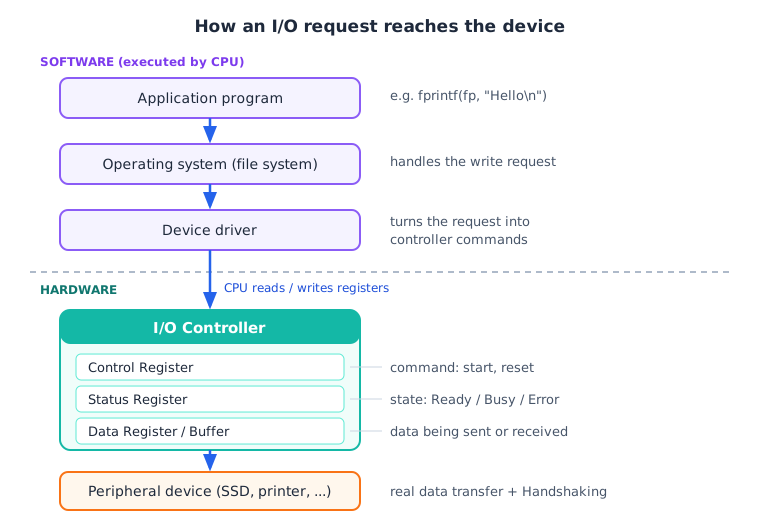
I/O Controller: hardware that relays communication between the CPU and peripheral devices.
Why it is needed: each device differs in data format, speed and behavior → if the CPU handled all of it directly, control would get complicated
I/O request path: application program → operating system (file system) → device driver → I/O controller → peripheral device
Controller vs Device Driver
Aspect Controller Device Driver What it is Hardware Software Location Motherboard, expansion card, inside the device Inside the operating system Role Actual data transfer with the device, state management Turns OS I/O requests into control commands, accesses controller registers Example USB Controller, SSD Controller USB Driver, Printer Driver
3.5.2 Communication Between the CPU and I/O Controllers
- System interconnect: the communication path linking the CPU, memory and I/O controllers. The CPU reads and writes controller registers through it
- When needed, the controller reports state changes to the CPU with an Interrupt
3.5.3 Data Transfer Between Devices and Handshaking
- Handshaking: two devices exchange control signals and status info to agree on when to send and when to receive. e.g. send data only when the printer is Ready
Purpose: confirm the receiver is ready, confirm delivery, coordinate timing between devices of different speeds, prevent data loss and errors
How the CPU learns it is done: 3.5.5 (Polling, Interrupt)
3.5.4 Serial and Parallel Communication and I/O Interfaces
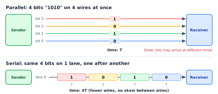
Parallel communication: sends several bits at once over several wires. e.g. 8 wires send 8 bits at a time
- Skew (bits that leave at the same time arrive at different times) can happen
Serial communication: sends bits one after another over a single path (Lane)
- Lane: one independent serial communication path. Using several together widens bandwidth
Data Rate: the amount of data sent over a communication path per unit time. Unit: bps (Kbps = 10³, Mbps = 10⁶, Gbps = 10⁹ bps)
- Maximum Data Rate: the theoretical maximum transfer rate of the interface spec
- Throughput: the transfer rate actually achieved in a real system. Maximum Data Rate ≥ Throughput
USB (Universal Serial Bus): the main serial interface for connecting peripherals
FireWire (IEEE 1394): a serial interface built for fast real-time transfer
- Peer-to-Peer: devices talk to each other directly. e.g. camcorder ↔ external storage
- Rarely used now, displaced by USB and Thunderbolt
USB vs FireWire
Aspect USB FireWire Basic method Serial Serial Who manages communication Host-centered Peer-to-Peer Typical use Keyboards, mice, storage, webcams Older camcorders, pro audio gear Key trait Versatility, compatibility, Plug and Play Real-time multimedia transfer - The key difference is not speed but who starts and manages communication
3.5.5 Polling and Interrupt
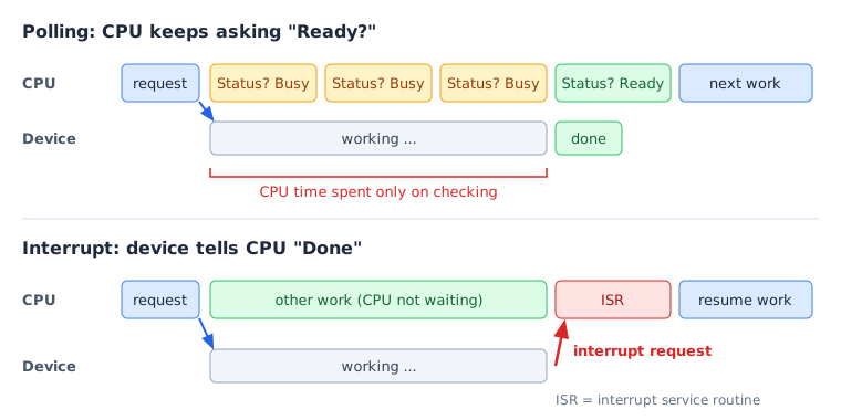
Why it is needed: the CPU is fast but I/O devices are slow and their completion time varies → the CPU needs a way to know when they are done
Polling vs Interrupt
Aspect Polling Interrupt How completion is detected CPU repeatedly checks device state Device notifies the CPU CPU waiting Spends CPU time on repeated checks Can do other work Strength Simple structure High CPU utilization Weakness Wastes CPU time when the device is slow Interrupt handling cost Best for Short, simple I/O I/O that takes long or is hard to predict - Even with interrupts, the CPU still has to move bulk data itself → 3.5.6 DMA
Full printing flow
- The user requests printing in an application
- The OS's Print Spooler stores the job in the Spool Queue
- The OS picks the first job in the queue
- The CPU runs the Printer Driver and checks the controller's Status Register
- If ready, it writes output data to the Data Register / Buffer
- Writes the start-printing command to the Control Register
- The controller passes data and commands to the printer, which prints
- When printing ends, the controller updates the Status Register + raises an Interrupt
- The OS handles completion and starts the next job in the Spool Queue
3.5.6 DMA (Direct Memory Access)
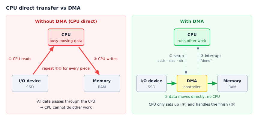
CPU direct transfer vs DMA
Aspect CPU direct transfer DMA transfer Data movement CPU stays involved Done by DMA CPU's role Reads and writes each piece Sets up the transfer + handles the result Bulk transfers Heavier CPU load CPU can run other instructions at the same time
3.5.7 Sharing System Resources and the Limits of DMA
DMA strengths: less repeated data movement by the CPU, lower CPU load for large I/O, the CPU runs other instructions during transfers, effective for bulk transfers in storage, networking and graphics
DMA limits: DMA also uses memory and the interconnect, large DMA transfers compete with the CPU for memory access, setup and completion handling add overhead, for very small transfers the setup cost can be larger
- DMA only reduces the CPU's data-moving load; it does not increase memory or interconnect bandwidth
Von Neumann bottleneck: limited data transfer capacity between the CPU and memory holds back overall performance. e.g. however fast the CPU is, it waits if data arrives late from memory
- Cause: the CPU fetches both instructions and data from memory to process them
- Using DMA does not remove the von Neumann bottleneck
Aspect DMA Von Neumann bottleneck Core problem CPU's load from moving I/O data Limited transfer performance between CPU ↔ memory Main target I/O device ↔ memory CPU ↔ memory Solution / mitigation Direct data transfer with DMA Cache, memory hierarchy, Prefetching Result Less CPU involvement Less CPU waiting on memory