
- Published on
CH6. Object-Oriented Analysis: Preliminary Design
- Authors

- Name
- seren-wib
Contents
- 6. Object-Oriented Analysis: Preliminary Design
- 6.2 UML
- 6.2.1 UML Overview
- 6.2.2 UML Diagram Types
- 6.2.3 UML Tools
- 6.2.4 StarUML
- 6.3 Functional Modeling: Use Case Diagram
- 6.3.1 Use Case Diagram
- 6.3.2 Use Case Diagram Example: Course Registration System
- 6.3.3 Use Case Diagram Example: Online Shopping Mall System
- 6.3.4 Benefits of Use Case Diagrams
- 6.3.5 Use Case Specification
- 6.4 Structural Modeling: Class Diagram
- 6.4.1 Elements of a Class Diagram
- 6.4.2 Types of Relationships Between Classes
- 6.4.3 Class Diagram Example: Course Registration System
- 6.4.4 Class Diagram Example: Online Shopping Mall System
- 6.5 Dynamic Modeling: Sequence Diagram
- 6.5.1 Design Target of Sequence Diagrams
- 6.5.2 Sequence Diagram for the Use Case 'Register Student'
- 6.5.3 Sequence Diagram for the Use Case 'Register Course'
- 6.5.4 Sequence Diagram for the Use Case 'Purchase Products'
- 6.5.5 How to Specify Use Cases
- 6.6 Representing Method Algorithms
- 6.6.1 Ways to Represent Algorithms
- 6.6.2 Specifying Algorithms in the Requirements Analysis Phase
- 6.7 HW/SW/NW External Interface Requirements Specification
- 6.8 Software Requirements Specification (SRS) Template
- 6.8.1 Overview
- 6.8.2 Functional Requirements
- 6.8.3 Domain Requirements
- 6.8.4 Non-functional Requirements
- 6.8.5 External Interface Requirements
- 6.8.6 Software Preliminary Design Content
- 6.9 SRS Evaluation Criteria
6. Object-Oriented Analysis: Preliminary Design
6.2 UML
6.2.1 UML Overview
UML (Unified Modeling Language): the standard modeling language for drawing a system design as diagrams. A common language so analysts, designers and developers can talk while looking at the same picture
6.2.2 UML Diagram Types
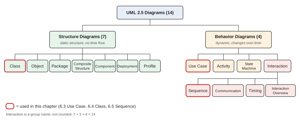
UML 2.5 diagrams: two groups, structure and behavior, 14 in total
- Structure diagrams: the static structure of the system. What exists and how it is connected, no flow of time (e.g. class diagram)
- Types: class, object, package, composite structure, component, deployment, profile (7)
- Behavior diagrams: how the system moves as time passes (e.g. sequence diagram)
- Types: use case, activity, state machine, interaction (4)
- Interaction diagrams split into: sequence, communication, timing, interaction overview (4)
- The three used in this chapter: use case → behavior, class → structure, sequence → behavior (interaction)
6.2.3 UML Tools
- Both commercial and open source: StarUML, Draw.io, Visio, Lucidchart, etc.
- The representative one is StarUML
6.2.4 StarUML
StarUML: the most popular commercial UML software. Aims at agile, concise modeling
- Features: multi-platform (Mac, Windows, Linux), UML 2.x compliant, SysML, ERD, DFD and flowcharts, open API, export to HTML docs
6.3 Functional Modeling: Use Case Diagram
6.3.1 Use Case Diagram
Functional modeling: drawing "what" the system does from the user's point of view. In object-oriented analysis it is expressed with a use case diagram
Use case: one function the system performs to give an actor a result (e.g. Register Course). One GUI menu = one use case
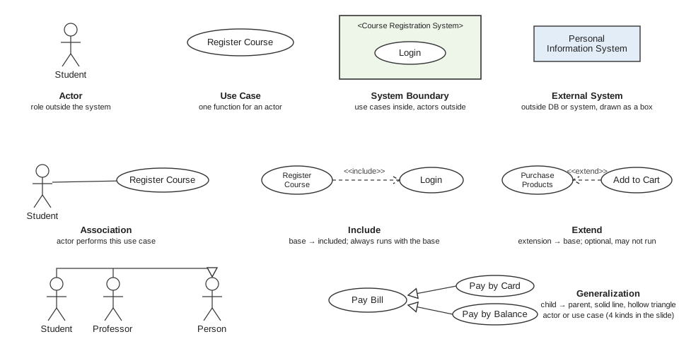
- Actor: a role outside the system that interacts with it. A stick figure. Not only people but also external systems (DB, character recognition system) are actors
- In the figure: the Student stick figure, the Personal Information System box
- Use case: an ellipse with a name. Two or more actors may attach to one use case
- System boundary: a large rectangle. Use cases inside, actors outside. The name is written as
<System Name> - External system: a name inside a rectangle, placed outside the boundary
- Line (association): between an actor and a use case. "This actor performs this use case"
- include: dashed arrow +
<<include>>. A sub use case that always runs when the base runs (e.g. Register Course → Login, Recognize → preprocessing, segmentation, classification, output)- Direction: base → included
- extend: dashed arrow +
<<extend>>. An exceptional or optional extension. It may not be called even when the base runs (e.g. Purchase Item ← No Change Left, Register Course ← Add to Cart)- Direction: extension → base. Opposite of include
- Generalization: solid line + hollow triangle, child → parent. Inheritance that lifts the common part up to a parent
- Four kinds: actor generalization (student, professor → person), use case generalization (Pay Bill → pay by card, pay by balance), between two extend use cases, between two include use cases
- Actor generalization helps find inheritance in the next step, the class diagram
- Slide note: p.29–30 treats register, cancel, change and view course as extends of Login, while p.32 says Register Course includes Login. When drawing, stay consistent: required means include, optional means extend
- Front-end/back-end (p.41): use case = a front-end (JSP, PHP, app) menu action, class method = back-end (Java, C#, Python) insert, delete, update, retrieve
6.3.2 Use Case Diagram Example: Course Registration System
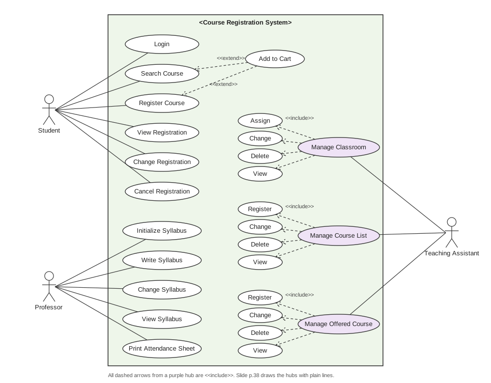
- Drawing order: stakeholders → actors, verbs in the requirement sentences → use cases, a function every user shares (login) becomes a shared use case
- The classroom, course list and offered courses that the teaching assistant manages each get four use cases: register (assign), change, delete, view. The slide ties them to a purple hub ellipse with plain lines
- Add to Cart is an extend of Search Course and Register Course
6.3.3 Use Case Diagram Example: Online Shopping Mall System
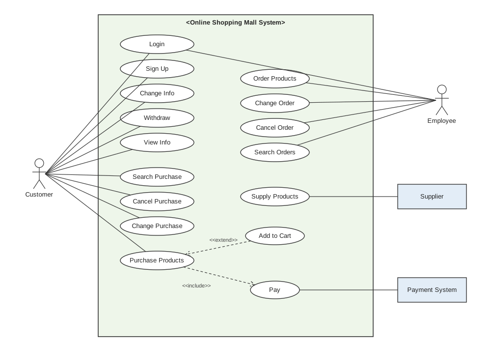
- Two external systems: supplier (Supply Products), payment system (Pay)
- Purchase Products → Pay is include (required), Add to Cart → Purchase Products is extend (optional)
- Slide p.40 note: the customer still has "cancel course registration" (a copy-paste slip), and the extends arrow points opposite to the body rule (extension → base)
6.3.4 Benefits of Use Case Diagrams
- Estimate system complexity and cost from the list of business goals
- Capture real requirements early in design
- Scenarios in natural language, so even customers and managers understand
- Identifying extension use cases and exceptions makes complex requirements easier to define, saving developer time
- Identifying the development boundary prevents scope from growing or shrinking
- Focus on "what", not "how", which prevents premature design
- Use cases convert directly into test cases
6.3.5 Use Case Specification
| Use case | User story | |
|---|---|---|
| Focus | How the system works, the sequence of user-system interactions | The benefit gained from an activity, what the user will do |
| Detail | Concrete. Later becomes a method algorithm | Less documented, details left out on purpose |
| Used for | Developers and testers understanding every system step | Starting conversations in agile (Scrum) meetings |
- Both identify users and describe goals, but they are not interchangeable
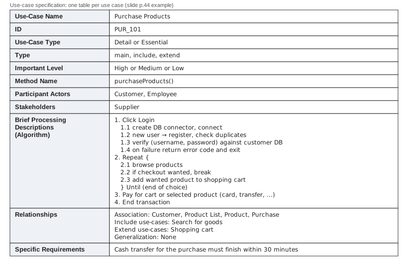
- One specification table per ellipse in the diagram
- It has a Method Name → a use case leads to a method. Brief Processing Descriptions lead to the 6.6 algorithm specification
- Specific Requirements hold non-functional requirements (cash transfer within 30 minutes)
6.4 Structural Modeling: Class Diagram
6.4.1 Elements of a Class Diagram
Structural modeling: drawing the static skeleton of the system (what exists and how it is connected). Tools are class, object, deployment, package, composite structure and component diagrams; the class diagram is used the most
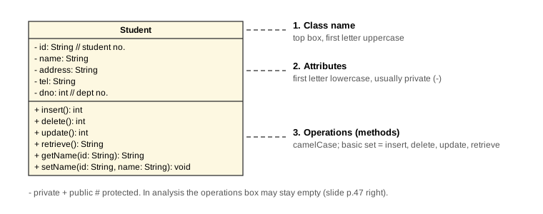
- Class box: a rectangle with three compartments
- In the figure: name, attributes, operations from the top
- Class name: top compartment. First letter uppercase (slide notation:
Class 학생(Student)) - Attributes: middle compartment. First letter lowercase (e.g. student number, name, address, phone, department)
- Access modifiers: private, protected, public. Attributes are usually private
- Operations (methods): bottom compartment. First letter lowercase, following words capitalized (e.g. getName, setAddress)
- Basic operations: insert, delete, update, retrieve
- In analysis you may leave the operations compartment empty and draw only up to attributes (p.47 right; the example diagrams have two compartments too)
6.4.2 Types of Relationships Between Classes
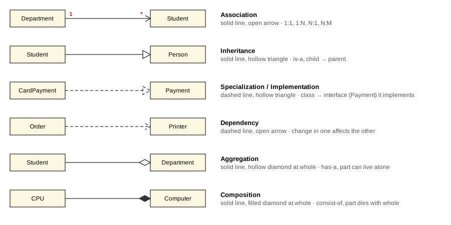
Relationships between classes: logical connections between classes. Six types per the slides
| Relationship | Line | End | Meaning | Example |
|---|---|---|---|---|
| Association | solid | open arrow | 1:1, 1:N, N:1, N:M correspondence | Department 1 — * Student |
| Inheritance | solid | hollow triangle | is-a, child → parent | Student → Person |
| Specialization / implementation | dashed | hollow triangle | put the parent first, then find the children | Person → Student, Professor |
| Dependency | dashed | open arrow | a change in one class's structure or behavior affects the other | when one class contains another |
| Aggregation | solid | hollow diamond (whole side) | has-a, the part can live on its own | Department ◇— Student |
| Composition | solid | filled diamond (whole side) | consist-of, a part of. Deleting the whole deletes the parts | Computer ◆— CPU, memory |
- Association multiplicity: write
1,*,0~*at both ends of the line- 1:1 student - record, 1:0~N employee - dependents, 1:N department - student, N:1 student - department, N:M student - offered course
- Expressing N:M: E-R uses a diamond (Takes); a class diagram puts an association class in the middle (
Takes: student number, offered course number, type, year, semester, grade) and splits both sides into 1:N - Generalization vs specialization: same diagram and implementation, only the direction of discovery differs
- Generalization: look at student and professor and extract the common part into person (bottom-up)
- Specialization: put person first and find student and professor (top-down)
- Aggregation vs composition: aggregation is a special case of association, composition a special case of aggregation. The difference is whether the part's lifecycle is bound to the whole
- Slide note: the p.49 symbol table draws aggregation and composition with dashed lines, but the p.54–55 examples use solid lines. The dashed triangle on p.49 (specialization) is the interface realization symbol in real UML
6.4.3 Class Diagram Example: Course Registration System
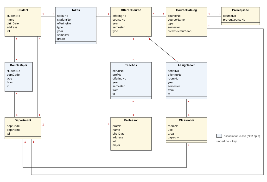
- Order: requirements table (p.57) → extract classes from nouns (p.58 cloud: student, staff, department, syllabus, course list, offered course, space) → E-R → class diagram
- Every N:M becomes an association class: Takes (student - offered course), Teaches (professor - offered course), AssignRoom (offered course - classroom), DoubleMajor (student - department)
- Points to watch (p.60)
- Association classes searched often (Takes, Teaches) get an extra attribute such as a serial number to speed up search. Some data duplication results
- Student - department is N:1, but minors, double majors, teacher training and convergence majors exist, so put two associations between the two classes (one direct line + one through DoubleMajor)
6.4.4 Class Diagram Example: Online Shopping Mall System
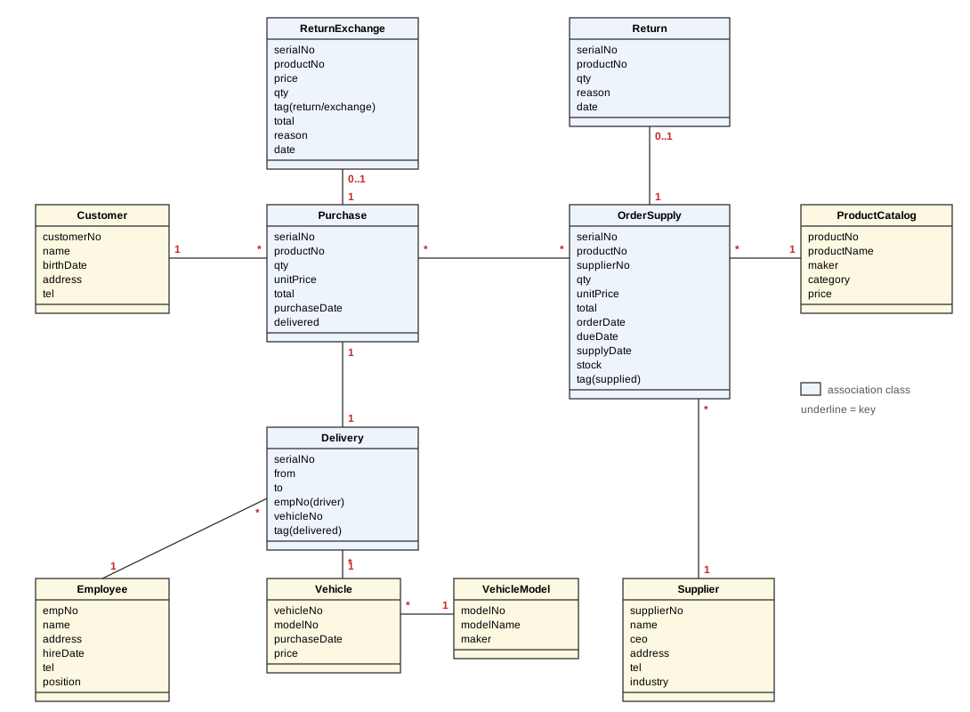
- Same order as 6.4.3: requirements table (p.61) → E-R (p.62) → class diagram (p.63)
- Association classes: Purchase, OrderSupply, Delivery, ReturnExchange, Return
- ReturnExchange and Return are
0..1: a purchase or order may have no return - Slide note: the p.62 caption is copy-pasted as "class extraction for the course management system"
6.5 Dynamic Modeling: Sequence Diagram
6.5.1 Design Target of Sequence Diagrams
Dynamic modeling: drawing how the system moves over time (timing and order of work, control flow)
- State: a situation an object is in under some condition during its life (e.g. order "awaiting payment")
- Transition: a change of state (awaiting payment → paid)
- Event: the occurrence that triggers a transition (clicking the pay button)
- Action: a basic operation triggered by an event that is not interrupted
- Diagrams for dynamic modeling
- Interaction diagrams: sequence diagram, collaboration diagram (the communication diagram in UML 2)
- State transition diagram
- Slide note: p.64 says "the state transition diagram is subdivided into two kinds", but it is the interaction side that splits in two (p.65)
Sequence diagram: a time-ordered drawing of which messages, and when, users, screens, objects and external systems exchange while one use case runs (e.g. press the register button: menu → look up offered course → cart → save registration)
- Placed next to its use case to help understand that use case's processing algorithm
- In the end it is the order of method calls between front-end objects
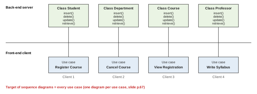
- Design target = every use case: one sequence diagram per use case
- In the figure: each front-end use case box at the bottom is one sequence diagram, calling CRUD methods of the back-end classes at the top
- Links: 6.3 use case = front-end menu, 6.4 class = back-end data and CRUD, 6.5 sequence = the order of method calls when one menu is pressed
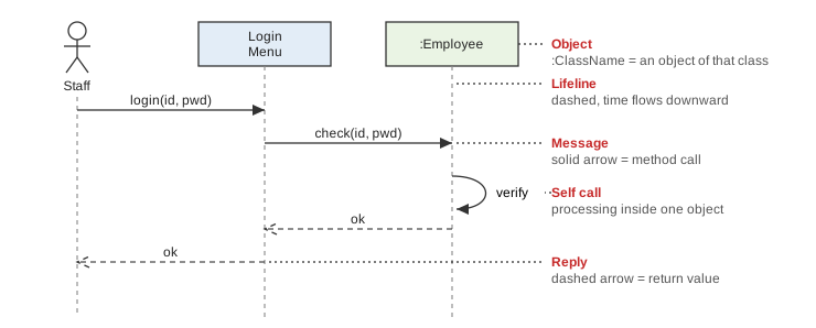
- Actor: stick figure, far left
- Object: rectangle,
:ClassName(e.g.:Student= some object of the Student class). Menu screens also stand as objects - Lifeline: vertical dashed line below an object. Time flows downward
- Message: solid arrow + method name (e.g.
check(id, pwd)) - Reply: dashed arrow + return value (e.g.
ok,Not exists) - Self call: a curved arrow returning to itself. Processing inside one object (e.g.
Input data,Choose(sectionId))
6.5.2 Sequence Diagram for the Use Case 'Register Student'
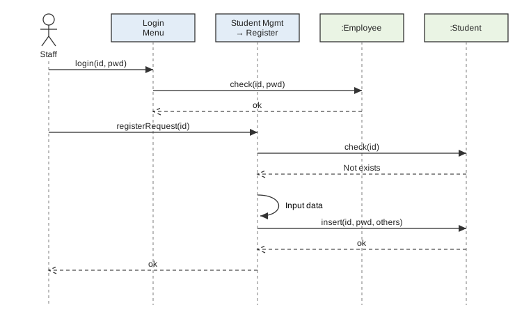
- Pattern: check login → duplicate check with
check(id)(Not exists) → input →insert→ ok
6.5.3 Sequence Diagram for the Use Case 'Register Course'
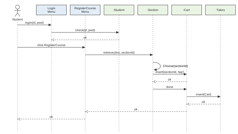
- Pattern: login → look up offered course with
retrieve→Chooseself call → cartinsert→insert(Cart)into:Takes→ ok :Section= offered course,:Takes= the 6.4 association class Takes, cart = the 6.3 extend "Add to Cart"
6.5.4 Sequence Diagram for the Use Case 'Purchase Products'
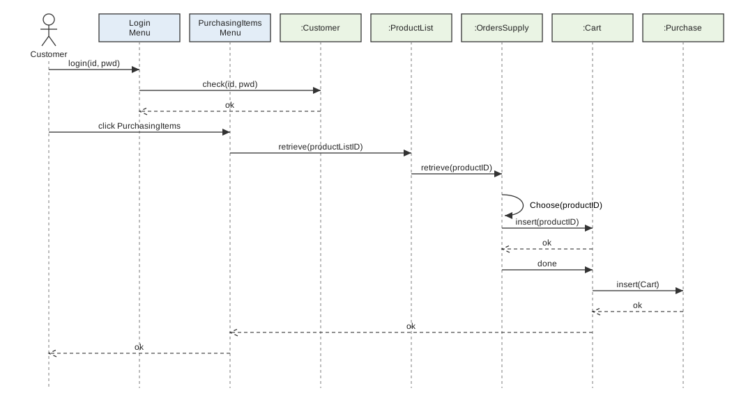
- Same pattern as 6.5.3, only object names differ:
:ProductList→ look up:OrdersSupply→:Cart→:Purchase - The same use case as the 6.3.5 specification example (PUR_101)
6.5.5 How to Specify Use Cases
- A sequence diagram is the steps of the use case specification's Brief Processing Descriptions (algorithm) redrawn as messages between objects (no slide; the template is the 6.3.5 figure)
6.6 Representing Method Algorithms
6.6.1 Ways to Represent Algorithms
- Four ways: pseudocode, flowchart, natural language (English, Korean), ordinary programming language
Pseudocode: "fake code" mixing natural language with programming language structure. More precise and concise than natural language, but there is no standard (e.g. IF stock > 0 THEN sell ELSE soldOut ENDIF)
6.6.2 Specifying Algorithms in the Requirements Analysis Phase
Method algorithm specification: attaching a header comment block + body algorithm to each method (e.g. insertionSort header block + insertion sort code)
- Header block fields: Method ID, Interface (function signature), Function (one line on what it does), Parameter, Return value
- Goes into SRS item 9, "method algorithm specification of classes", in this form for each method
6.7 HW/SW/NW External Interface Requirements Specification
| Kind | Counterpart | Example |
|---|---|---|
| User interface (UI) | a person | course registration menu screen (including GUI spec) |
| Hardware interface (HW) | a machine | barcode scanner, card terminal |
| Software interface (SW) | a program | DB (MySQL), libraries, operating system |
| Communication interface (NW) | sent over a network | payment confirmation email |
6.8 Software Requirements Specification (SRS) Template
- Overall flow: overview → what (functional, domain) → how well (non-functional) → how it meets the outside (interfaces) → how to build it (preliminary design) → review, conclusion. Items 1–5 are chapter 4 requirements analysis, items 6–9 are chapter 6 preliminary design
SRS: the results of requirements analysis bundled into one document. The baseline where the development team and the customer agree "this is what we build"
6.8.1 Overview
- 1.1 development goals, 1.2 development scope and content, 1.3 product value, 1.4 target customers, 1.5 usage scenarios, 1.6 work breakdown structure (WBS), 1.7 glossary
6.8.2 Functional Requirements
- 2.1 use case analysis, 2.2 data processing flow diagram, 2.3 system tasks, 2.4 management functions, 2.5 transaction processing tasks, 2.6 details of tasks performed on every screen
6.8.3 Domain Requirements
- No sub-items. The rules of the business domain itself (e.g. at most 24 credits per semester)
6.8.4 Non-functional Requirements
- 15 items: performance, reliability, load and stress, security, operation (capacity), usability, compatibility, stability and availability, scalability, maintainability, installation, recovery, legal regulation and environment, risk analysis and constraints, documentation deliverables
6.8.5 External Interface Requirements
- 5.1 user interface requirements and GUI specification (or design), 5.2 hardware, 5.3 software, 5.4 communication
6.8.6 Software Preliminary Design Content
- 6 Functional modeling: use case diagram, use case specification
- 7 Structural modeling: class diagram, CRC cards and class specification, DB schema specification, abstract and interface class specification, other data structure specification
- 8 Behavioral modeling: sequence diagram per use case, activity diagram (optional)
- 9 Method algorithm specification of classes: the largest part
- 10 Requirements review results (criteria in 6.9 evaluation criteria), 11 conclusion, appendix, references
- CRC card: Class, Responsibility, Collaborator. A technique that writes one class per card with its name, responsibilities and collaborating classes (not explained in the chapter body)
- The 6.5 title says "dynamic", the SRS template says "behavioral" modeling. Same thing
6.9 SRS Evaluation Criteria
SRS evaluation criteria: standards for judging how well a requirements specification is written. Per the slides, the IEEE 830:2009 quality model, 6 criteria
| Criterion | In one line | Violation example |
|---|---|---|
| Completeness | Is everything needed there, nothing missing (requirements, classes and methods, use cases, figure and table labels, term and acronym definitions, all preliminary design deliverables) | glossary missing, a use case with no sequence diagram |
| Correctness (clarity) | Is what's written a truly needed requirement, written accurately | a feature the customer never wanted |
| Consistency | No conflicts or ambiguity inside the document (internal) or with higher-level documents (external) | max 24 credits in one place, 21 in another |
| Verifiability (traceability) | After building, can you confirm and trace that requirements are met | "respond quickly" (write "within 3 seconds" to make it verifiable) |
| Modifiability | Can it be changed easily, completely and consistently while keeping structure and style | the same requirement scattered in several places, so fixing one leaves the others out of sync |
| Readability and understandability | Can stakeholders easily extract and understand the content | only acronyms and jargon with no explanation |
- Completeness vs correctness: is anything missing vs is what's there right
- Consistency vs verifiability: do requirements conflict vs can you check them after building
- SRS item 10, "requirements review results", is filled using these 6 criteria